Circuit Diagram Of Centre Tap Rectifier
Solved 14) a centre-tap rectifier circuit consists of a Center tapped full wave rectifier : circuit, working & applications Centre tap full wave rectifier circuit diagram in 2021 circuit
Center Tapped Full Wave Rectifier Circuit Diagram
Rectifier wave tapped full center circuit diagram operation its contents Full wave rectifier op circuit Full wave rectifier graph
Center tapped full wave rectifier
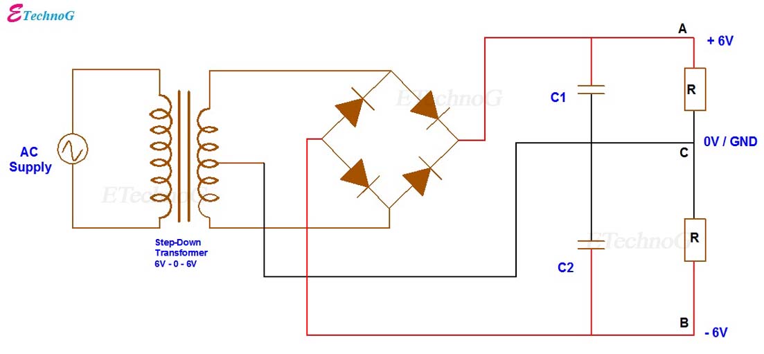
Wave full rectifier circuit tap centre tapped figure rectifiers bridge electronics representation shows belowRectifier wave full tapped center ratio turn current cycle positive path figure voltage negative daenotes [diagram] wiring diagram for rectifier and capacitorCentre tap full wave rectifier circuit operation,working,diagram,waveform.
Rectifier transformer tapped output input waveformCentre tap full wave rectifier circuit operation,working,diagram,waveform Center tapped full wave rectifierRectifier tapped transformer voltage diodes diode across load consists resistive.

Rectifier tapped operation
Circuit diagram of centre tap rectifierCenter-tapped full-wave rectifier operation What is full wave rectifier ?What are full-wave rectifiers? definition, centre-tap full-wave.
Rectifier rectifiersDifference between full wave bridge rectifier and full wave center tap Rectifier advantages disadvantages electronicscoachBipolar output full wave bridge rectifier with center tapped.
Full wave bridge rectifier calculator
Full wave rectifierRectifier voltage waveform circuits ground Full wave controlled rectifier circuit diagramRectifier circuit diagram.
Explain with circuit diagram and waveform working of center tap fullCenter tapped full wave rectifier circuit diagram Difference between centre tapped and bridge rectifier (with comparisonCircuit diagram of centre tap rectifier.

Tapped rectifier transformer coil understanding waves
Center tapped full wave rectifier definition principle benefitsRectifier wave full tap centre waveform circuit diagram working Rectifier tappedRectifier wave full circuit bridge voltage output working transformer tapped centre across load advantages consists.
Rectifier wave tapped full center voltage peak operation inverse diagram circuit opto signal proteus bidirectional isolators simulate itsFull wave rectifier operation The center-tapped full-wave rectifierUnderstanding what happens in transformer with a center-tapped primary.


Solved 14) A centre-tap rectifier circuit consists of a | Chegg.com

Center Tapped Full Wave Rectifier Circuit Diagram
![[DIAGRAM] Wiring Diagram For Rectifier And Capacitor - MYDIAGRAM.ONLINE](https://i2.wp.com/electric-shocks.com/wp-content/uploads/2019/03/Full-wave-Center-tapped-rectifier-circuit-diagram.jpg)
[DIAGRAM] Wiring Diagram For Rectifier And Capacitor - MYDIAGRAM.ONLINE

Full Wave Rectifier - Definition, Circuit Construction, Working, Advantages

Center Tapped Full Wave Rectifier Definition Principle Benefits - Riset

Difference between Centre Tapped and Bridge Rectifier (with Comparison

Full Wave Rectifier Op Circuit | My XXX Hot Girl

Full wave bridge rectifier calculator - customerlasem